
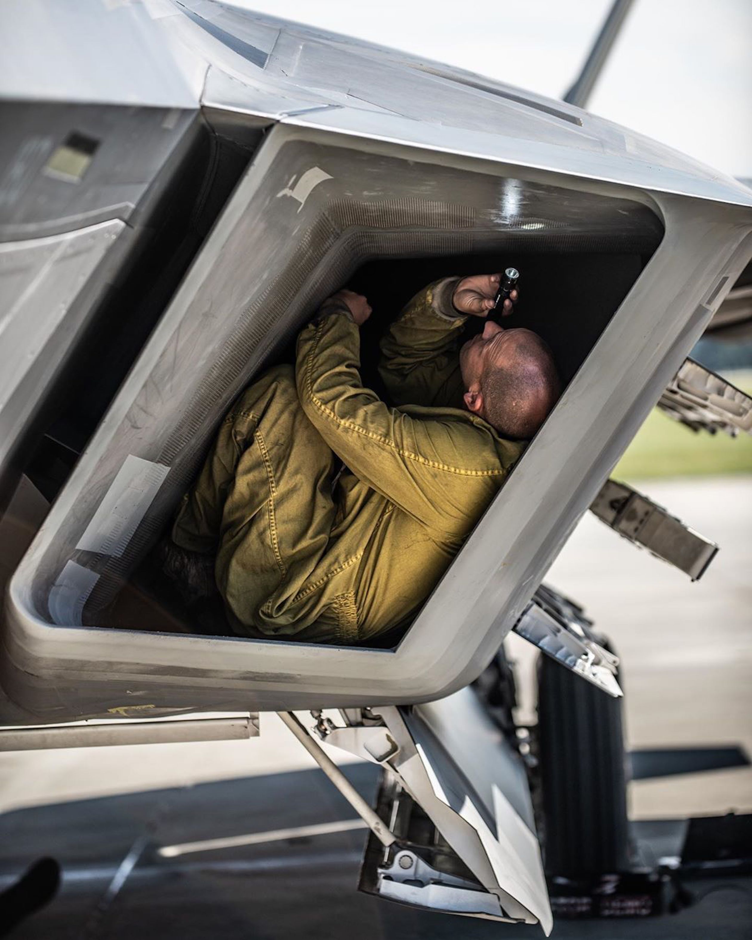
Jet engines need to breathe air that is travelling slower than the speed of sound, so how do you do that on an aircraft intended to travel far faster? We asked Jim Smith to take his torch and look up the intakes of the modern fighter aircraft.Â
Three main considerations drive the type of intakes used for supersonic aircraft.
The first is that the air delivered to the compressor face of the engine has to be subsonic (slower than the speed of sound). The reason being that supersonic airflow would create shock waves to form across the fan and compressor blades, which would not only severely disrupt the normal flow through the engine, but could cause destructive vibrations which could destroy the engine.
The second is that, to maximise engine thrust, the energy losses in slowing the air to subsonic speed must be minimised. Finally, for some recent aircraft, radar signature must also be minimised. A fourth general consideration is that the intake must be able to operate satisfactorily over a wide range of flight parameters, including not just speed and incidence, but also pitch, roll and yaw angles and rates.
The management of shock waves by the intake system is one of the key ways in which the supersonic flight airflow is reduced to subsonic speed at the engine face.
Intake forms
Pitot Intake

The simplest form of intake is the simple pitot intake, examples of which can be seen on early jet fighters such as the MiG-15, Dassault Ouragon and F-100 Super Sabre. At supersonic speeds a shock wave forms across the front of such intakes, and this form of shock wave is known as a Normal Shock (because the shock wave is at a right angle to, or Normal to, the flow).

This type of intake is very simple, has no weight penalty, and is relatively insensitive to flow direction, at least partly because there are no fuselage surfaces ahead of the intake to provide disturbances of the flow, and no boundary layer from such surfaces, which can provide another source of flow disturbance into the intake.
Why don’t all supersonic aircraft use these intakes? Well, as the flight Mach Number increases, the strength of the Normal Shock increases. This means that the pressure drop through the shock wave increases, reducing the efficiency of the intake. In addition, the temperature of the airflow will also rise. Both these factors reduce thrust, and aircraft with pitot intakes are only really efficient at Mach numbers up to about 1.6.
Variable Geometry Intakes – Cones and Ramps
Considering the discussion above, we can see that shockwaves are an important mechanism for reducing the intake airflow to a subsonic speed at the engine, but that a single Normal Shock becomes too strong and loses efficiency. What is needed is a means of producing the weakest possible shock system that still enables subsonic flow at the engine face. Shaping the inlet duct can assist in this, but generally some form of variable geometry is required so that the flow to the engine can be efficiently delivered over a range of Mach numbers.

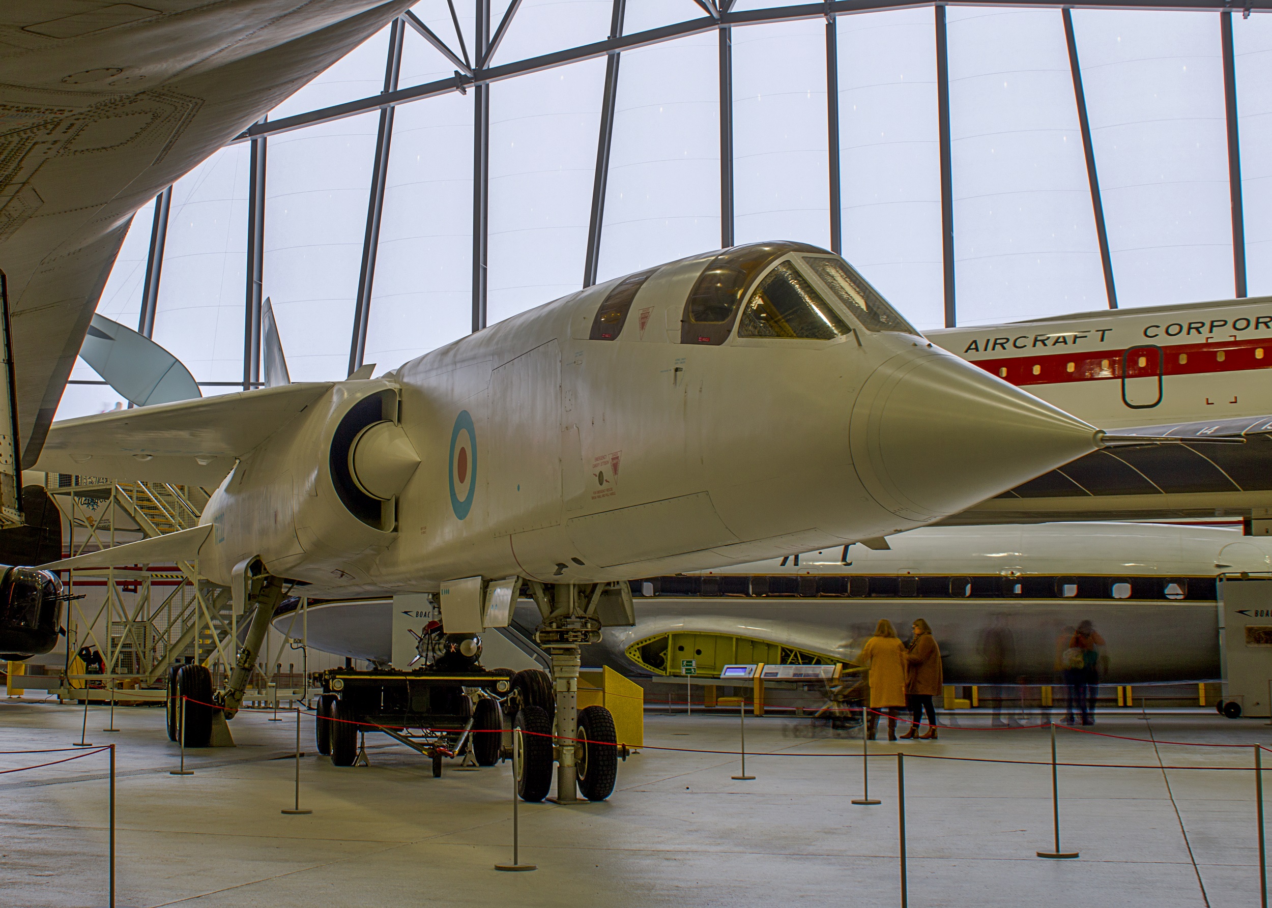
A simple way of doing this is to provide a conical surface in the inlet, which can be moved to generate a shockwave at an angle to the flow (typically between the point of the cone and the intake lip). This oblique shock allows a weaker and more efficient Normal Shock at the intake lip. This type of design is seen in the MiG-21 and BAC Lightning, and a similar approach can be implemented for side intakes using a moveable half cone to generate the oblique shock wave, as seen, for example, on the Mirage series of aircraft, from the Mirage III to the Mirage 4000. The side intake may be desirable if a large nose-mounted radar is to be carried.
These variable geometry intakes are capable of working effectively up to speeds around Mach 2.2.
Another way of generating an oblique shock wave system allowing efficient flight at high Mach numbers is to use variable ramps ahead of, or inside, the inlet. This achieves the same effect as the variable Mach cone, but can achieve higher efficiency. Because it is possible to use more than one ramp, and to vary the angles of ramps to suit the flight speed, multiple oblique shockwaves can be formed, reducing inlet airspeed as required, but minimising pressure and thermal losses.

This type of engine intake is used in many aircraft, but the F-4 Phantom provides a good example of a variable ramp intake. The efficiency which can be achieved is perhaps exemplified by Concorde, capable of super-cruising (flying supersonic without the use of afterburner) at Mach 2.02 and 54,000 ft. Another high-speed aircraft using this type of inlet is the MiG 31, which is capable of very high speeds – the maximum permitted Mach number is reported to be Mach 2.83 (Janes 1992-3).

The SR-71 is an example of a multi-shock conical inlet, with the multiple shocks arising from a combination of cone position, which locates the oblique shock, and inlet cone and duct shaping, which positions the Normal Shock. The variable geometry inlet was supplemented by auxiliary doors for lower speed flight, and a variable by-pass engine to ensure efficient flow through the engine at high speed. The complexities of coupling the variable geometry inlet to a variable by-pass engine resulted in a propulsion system capable of delivering very high cruise speeds in excess of Mach 3, but which could be very sensitive to varying conditions, leading to occasional engine ‘unstart’ issues.
Boundary Layer Diverters, Diverterless Intakes and Radar Signature Reduction.
Maintenance of stable flow conditions over a broad range of manoeuvre angles and rates is essential in a fighter aircraft. The development of early supersonic aircraft was plagued by engine-inlet related issues including shock wave ‘buzz’, adverse effects of gunfire, inlet flow instabilities, and unexpectedly low installed thrust.
For aircraft with side-mounted intakes (most aircraft not using a pitot intake) some of these issues arose from interactions between the flow on the aircraft fuselage and in the engine inlet. As a result, it was found desirable to stand the intakes off from the side of the fuselage, creating a passage to allow the fuselage boundary layer to flow past the intake without entering it and disturbing the flow to the engine. In many cases, further protection was achieved through the use of a splitter plate to ensure the separation of the boundary layer flow from the intake flow.
This type of arrangement, which is clearly visible on almost all jet aircraft with side intakes, is known as a boundary layer diverter. While this approach ‘does the job’ it also creates a deep channel alongside the intake which can increase significantly the radar signature, particularly in head-on aspects.
Head-on radar signature is particularly important for fighter aircraft because this is the aspect they generally present to opposition fighters and Airborne Early Warning aircraft. In addition, if untreated, the head on radar signature is likely to be large because of the fighter’s own radar, intakes, inlets and engines, cockpit, other sensor apertures and boundary layer diverter.
Treatments exist for many of these items through shaping, coatings and other measures, and, for a fighter with low observable aspirations, once the obvious major contributions have been addressed, the boundary layer diverter can become an issue.
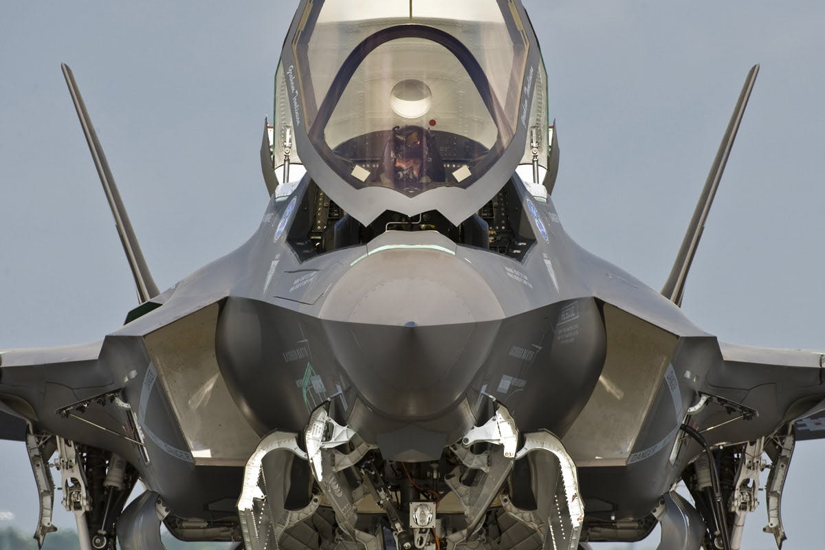
In developing the F-35, Lockheed-Martin has developed a diverterless supersonic intake, consisting of a shaped ‘bump’ on the fuselage side, which acts like a ‘rock’ in the fuselage boundary layer ‘stream’, causing the boundary layer flow to part and avoid flowing into the intake. The ‘bump’ is coupled with a forward swept intake cowl, and it is claimed this offers a light-weight solution to providing an efficient intake for a supersonic aircraft, with the added advantage of avoiding the radar signature of a boundary layer diverter. This approach has also been used on the Sino-Pakistani JF-17 Thunder aircraft.
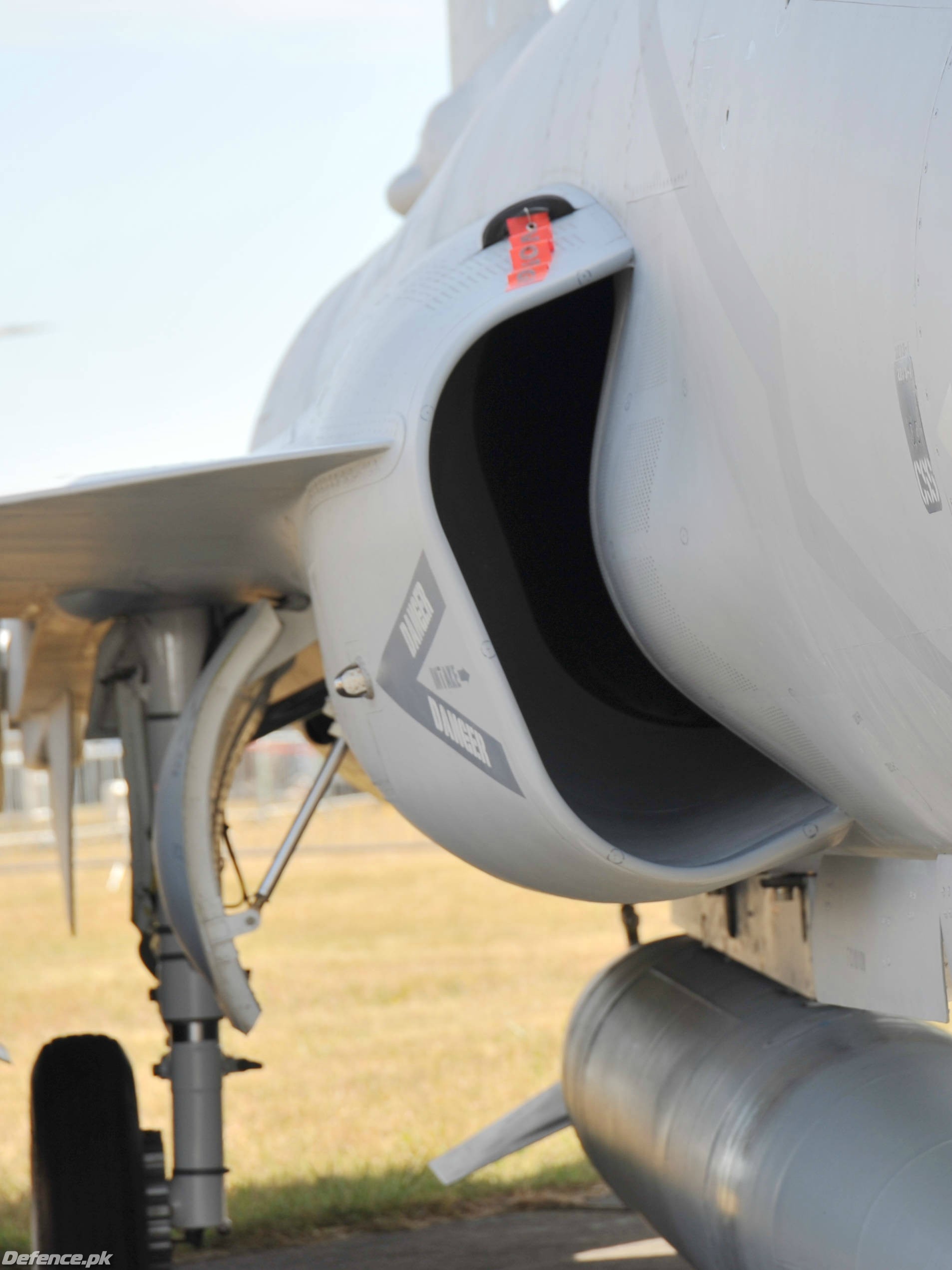
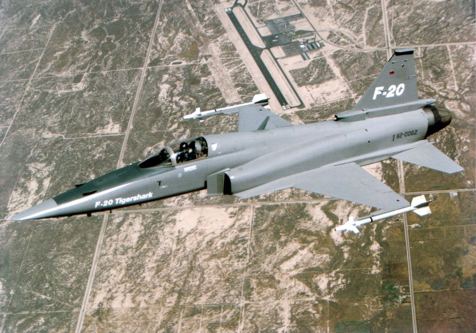
It is, perhaps, worth noting that neither the intake, nor the diverter system has any variable geometry. Consequently, the intake system is likely to act like a pitot system in some ways, limiting efficient flight speeds. This is perhaps less of an issue for the F-35, because it has very low signature, and also because it will be limited to about Mach 1.6 by wave drag. One might wonder, however, about the trade off for the JF-17, where perhaps a F-20 Tigershark-like intake with a variable ramp might, with a suitable engine, allow higher performance in the Mach 2 range.
It is worth noting that the F-22 Raptor retains a boundary layer diverter, doubtless treated with RAM, combined with a number of other measures to reduce intake and engine signature in the forward aspect. The quoted maximum speed of Mach 2.25 is extremely creditable for an aircraft with a fixed inlet. The inlet itself is at an oblique angle to the airflow, and this, together with careful shaping of the internal duct may not only to reduce signature, but also increase the efficiency of pressure recovery compared to a simple pitot intake, like the intakes of Concorde and the MiG 31, but without a variable internal ramp.
Interestingly, the intake of the YF-23 was also diverterless, but this was achieved using flow control rather than the geometric bump featured on the F-35. A technique called boundary layer suction was used to remove the boundary layer from the relatively short surface ahead of the intake. This is not a new technique, and indeed, is used on the boundary layer diverter plates of some aircraft, including the Typhoon. The end result for the YF-23 was a notably clean and simple looking intake. Like the F-22, one would expect shaping of the internal duct to be used to control the position of the oblique and normal shock waves and achieve an efficient intake system.
References: Aerodynamics for Naval Aviators NAVWEPS 00-80T-80 Naval Air Systems Command;
Janes All the Worlds Aircraft (various)
Lockheed SR-71 The Secret Missions Revealed, Paul F Crickmore
Wikipedia on JF-17 and F-22
Sadly, we are way behind our funding targets. This site is entirely funded by donations from people like you. We have no pay wall, adverts (any adverts you see on this page are not from us) or subscription and want to keep it that way– please donate here to keep this site going.
Thank you.Â